The Building of the Card Enterprise

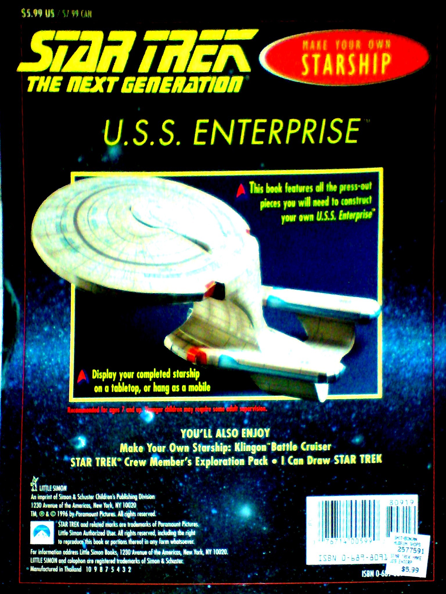
Ambling through the Smithsonian museum one day circa 1996 my future darling girlfriend came across this book-kit to make a starship Enterprise out of card, and had the good sense to purchase it as an impromptu treat. She procrastinated over assembling it for 16 years, but when I saw it naturally I couldn’t resist but take it and build. On first impressions it seems like a simple push-out-and-slot-together kit that might be assembled by seven year olds (as advertised on the back cover, figure 1b), but one quickly realises on perusing the instructions printed inside the covers that glue and degrees of planning, cunning and patience are required.
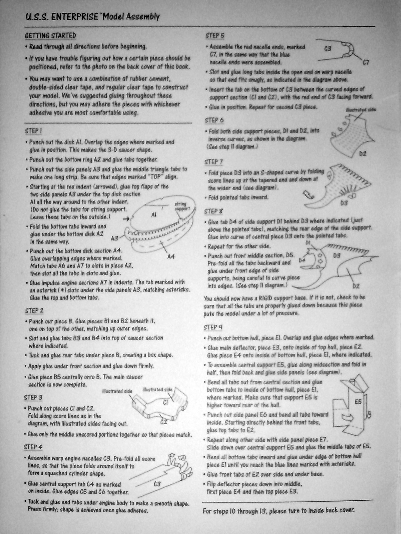
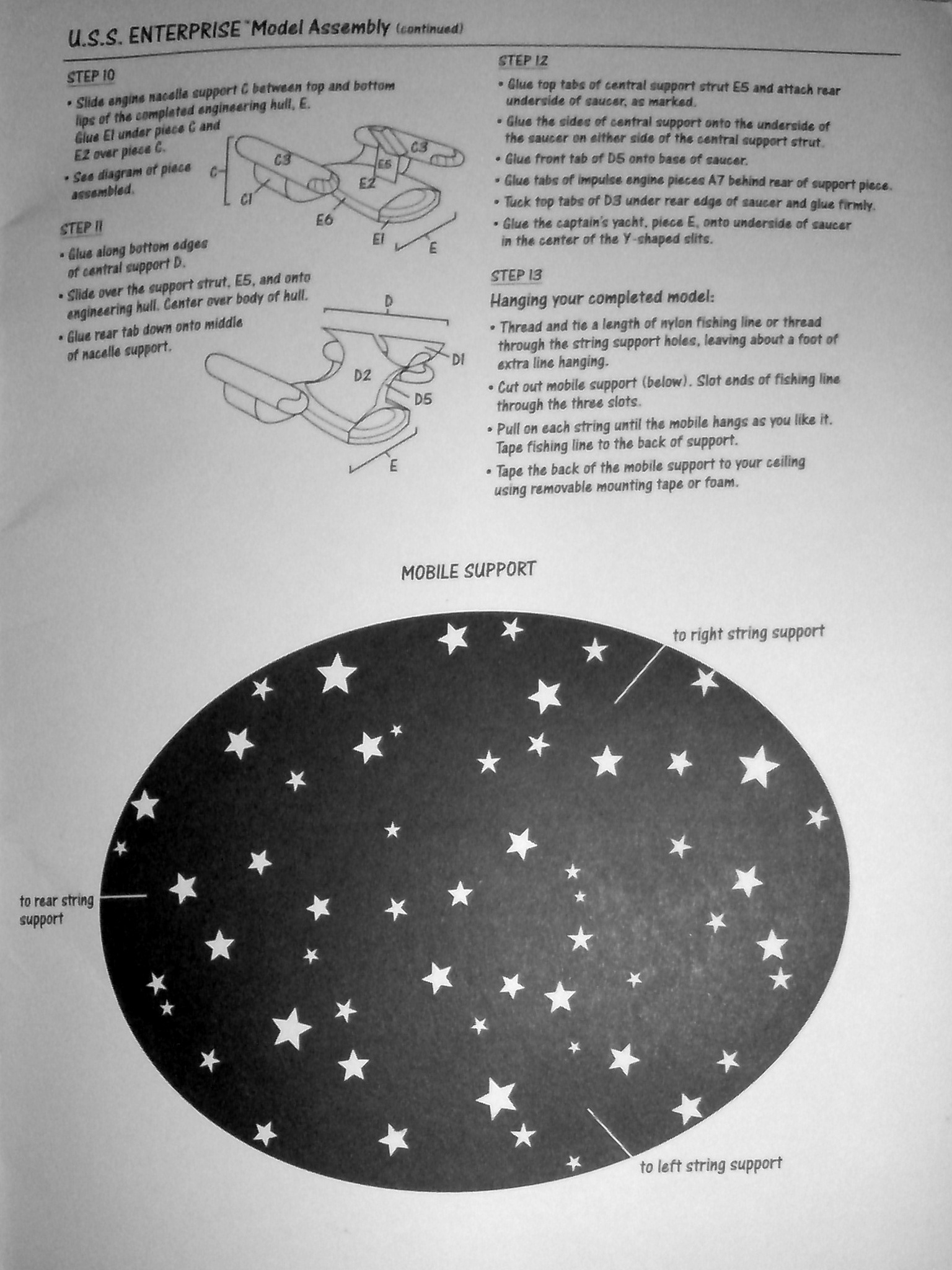
The instructions provided (figure 2) are in fact absolutely top-notch, and include such gems of advice as that you should familiarise yourself with the complete build before you start, and use whatever adhesives (contact, cement, double-sided tape, etc) that you feel comfortable with in each situation; advice which turns out to be immensely valuable and precisely the guidance an intrepid constructor requires, although I think I would stop short of using Sellotape or such like. All parts of the model itself are clearly labelled on surfaces which finish up out of view on the inside, and all surfaces which finish up in view are shiny and printed with the ship’s surface detail, which at first sight appears cartoony and cheap, but eventually suits the finished build quality and degree of detail very well, to produce a model which simply looks like it had been a whole lot of fun to assemble.
The construction exercise took place over an eight day period, rests being required so that glue could become properly dry and binding before the parts were stressed during later parts of the build—the stresses mainly caused by the need to get fingers deep inside structures in order to press seams together.
Most of the model was glued with a stick of solid paper contact adhesive, but I did resort to modelling cement for some of the latter parts of the build. The contact adhesive works best overall as it is quick to bind and set, goes invisible, bonds paper very well and does eventually set quite hard, lending something to the overall structural rigidity. It does suffer the disadvantages that you need unfettered access to the surfaces to be able to apply the glue, and you need to be able to get your fingers squarely on both sides of a join in order to press it together firmly.
Unfortunately as the build of the model nears completion, both the above disadvantages come to the fore and actually prohibit the use of contact adhesive. The model suffers for the fact that at some point you have to close in a mostly convex polyhedron (with curved faces, and edges). The fundamental problem is that you can construct a closed body as long as you can get your fingers inside it to squeeze tabs together, but there inevitably comes a juncture at which the body is finally closed off and you just can’t get in, and that is where the contact adhesive fails to be of use; pressing a joint entirely from the outside only serves to crush the model. At this point I took to applying modelling cement which can be made to run into seams where joins are needed, and doesn’t need any force applying to work. The substantial disadvantages are that the glue takes a long time to dry—even to acquire a satisfactory adhesion—, and gets squeezed out of the join and consequently onto fingers; I found myself many a time glued to the work and pulling it apart in the process of reclaiming said digits.
Out of exasperation I eventually took pains to acquire split pins and small paper clips to hold seams together while the glue dried, where it was possible.
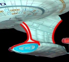
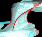
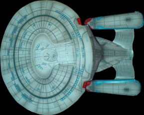
Structurally, the best part of the model is the neck. The back corners are compound curves (figure 5) joined by gluing many (fifteen or twenty?) triangular tabs. The end result is an impressively rigid piece of engineering. The saucer section successfully gets its rigidity from the formed cone shapes top and bottom, and the main body gets rigidity from a clever compound join around the circumference of the deflector dish (at the front of the main body), which also serves to provide finger access inside the main body and to pop the model into shape. Surprisingly the edge of the saucer section turned out well as this was a fiddly mess of about 50 triangles, top and bottom, which needed gluing all the way around inside the rim. However, a similar exercise around the perimeter of the main body was much less satisfactory—despite the remarks above, there was much less room to get fingers in and so it proved impossible to get a clean bond all the way around in one go. Modelling cement came to the rescue!
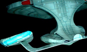
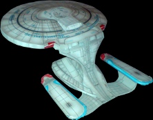
The nacelle supports are the worst aspect of the model (see figures 6 and 8), which amount to bits of bent card with scant control over the forming; these shapes are very wrong to begin with (the nacelles are too low relative to the position of the saucer), and are so feeble as to be barely capable of actually supporting the nacelles (they are not maintained in a parallel, horizontal attitude). It is difficult to make a thin shaped curve out of card, and the solution adopted, to place two pieces next to each other, glued over the entire contact surface and then stressed so that the amount of card on the inside of the bend is shorter than the outside, is a fair attempt at a solution to this problem. But the end result is still flimsy and not the correct shape. Unfortunately the televised design, being intrinsically minimalist, shows no buckles, webs or ridges, so it would seem that the only way forward with card is to give the supports some thickness and inside the cavity put some sideways tie strips, with plenty of tabs to allow the gluing to provide integrity. The designers of the kit probably thought that this was too fiddly for a toy. The nacelles themselves have poorly defined shapes, capped with rounded ends which are not realized well (difficult to do with card, but still...).
In the long run the model does, unfortunately, pull itself apart. The glue, whatever variety, does eventually fade and the fact that all parts of the assembly are under tension means that seams split and the model eventually fails without careful maintenance. So if you build one, make the most of it while it lasts, and take many pictures for posterity, or, better still, build a website around your building experiences!
It is interesting to contemplate the meta-engineering and design trade-offs that went into making the underlying product: the pop-out book.
- Use an even number of sheets (US letter sized?)
- Minimise the amount of wasted card
- Try to keep the build simple enough for seven year olds
- Make it rigid enough to stand on a table and support its own weight, or to hang from three suspension points
- Make it easy to push the pieces out, but at the same time make the book stable—not fall apart—on its own
- Aim to be as close to the ship depicted in the television series as possible, but stay within the limitations of a card cut-out
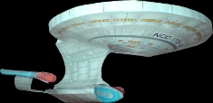
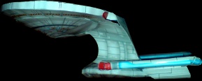
The trade-offs taken with regards to the overall shape of the finished model are also interesting. It is clear (figure 8) that the model is stumpier than the televised version of the ship, with the neck section standing more perpendicularly off the main body, the main body being relatively short, and the nacelle supports being very short. Clearly all this was done in the name of final rigidity.
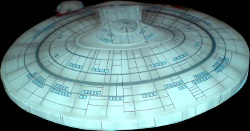
It is also noticeable how eccentric, not circular, the saucer section is (figure 8b). I had always percieved it to be perfectly circular, but on closer examination of the television series and web resources it transpires that the saucer actually is oval. It would appear that the model exaggerates this, though, and that may be both due to the shape of the pages in the book and the fact that a large overhang creates stresses which are difficult to contain in a card structure.
Building this model has opened my eyes to the true physical geometry of this starship. We see the thing zipping around the television screen: a saucer and two nacelles joined by a funny body, (and always the ‘right’ way up!) The model emphasises the fact that the neck has to be a substantial piece of engineering, having to support under gravity (and presumably under impulse acceleration) not only the weight but also the implicit twisting moments that the large overhang of the saucer section induces. Most of all, I now appreciate just how stupid a design this is for a starship. But then, maybe ships will be plain trendy in the 24th Century?
This incarnation of the Enterprise breed of ships is very much a design of the nineties. Coming out of the square age of the eighties and having computer-aided design tools and computer-graphic renderers that can deal with curves, the designers obviously decided that a curvaceous successor to the original Enterprise was in order, that it should look more aerodynamic, and that the ‘thrust line’ through the nacelles should pass closer to the centre of mass, hence the nacelles taking up a much lower position than the original which had them perched way above the saucer section. As the assembly of the model progresses you realise that you are spending great efforts making structure that totally is not necessary for a space-going vessel. I really don’t know what to make of the separating saucer business, but fortunately the model doesn’t care for it either.
And so I find myself faced with the following difficult question. Do I call it a day and sit back to enjoy the fruits of my labours (figure 9), or is this just the beginning of a never-ending project to make an improved model? The current fad in 3D printing aside, technology has moved on sufficiently in the sixteen years (more!) since this kit was developed, and, —provided a cheap printer can be found with a relatively flat transport in it, so that it will print on various thicknesses of card without needing to bend them—, it is entirely possible to produce a kit like this from scratch at home. I am so tempted to start writing a PostScript program (yes, PostScript is a programming language, not merely a printer format; thirty years before the current gamut of 3D graphics cards and their attendant dedicated processors, PostScript blazed a trail with a reverse-polish stack-based language that revolves around transformation matrices, glyphs and colour graphics), which calculates the compound curves necessary to make a rigid model the correct shape and prints the surface detail with all the resolution and colour you could want. The only problem is the matter of cutting and scoring to obtain formable pop-out parts, but trusty scissors or scalpel will surely do the job.
What would I do differently? Well, the nacelle supports (surprise!) would be far more engineered for strength, and researched to get a more accurate shape and nacelle positioning (halfway between the extreme top and bottom of the model, horizontal and parallel). I would work at getting the cracks (open seams) down, and look at a better build order so that the final bonds can be established between already sturdy edges which can be pushed together without crushing the model. I might look at using a variety of different thicknesses of card, perhaps making a sturdy internal scaffolding of thicker card and then laminating successively thinner layers over it (presumably a real ship would not depend on its skin for its strength, but on internal sub-structure?)—or is this defeating the aim of the exercise, to make a model using a minimum (one!) variety of materials?